John Oxley Restoration
Update January 2008
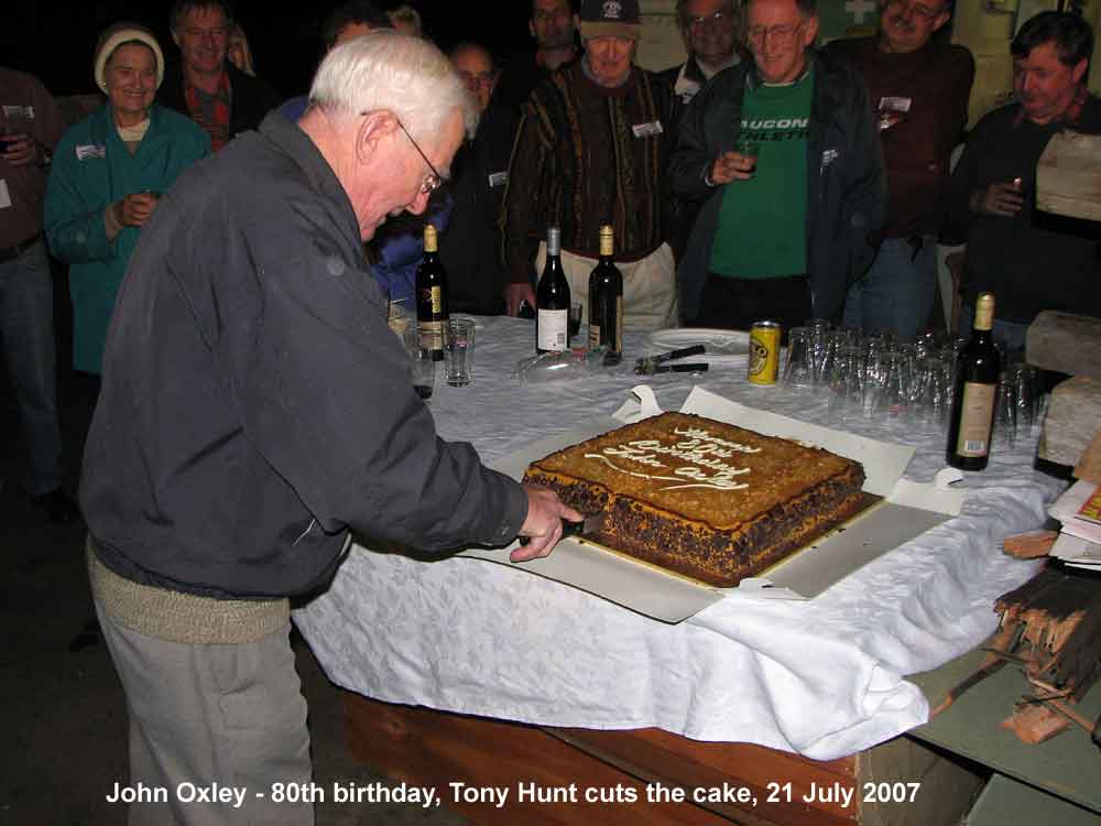
John Oxley 80th Birthday
80th Birthday Celebration
 Since the last report, John Oxley has celebrated 80 years since its launch into the White Cart (river) on 20th July 1927. Research through Google Earth plus some early maps of the Paisley locality soon showed where John Oxley was built. While the actual works no longer exists, it is still possible to see clearly the tracks left by old ship building slips.
A congratulatory letter from the Provost of Renfrewshire has been received, it is clear that it is a long time since shipbuilding in this part of the world was practiced. They were surprised that part of their industrial and shipbuilding past had survived for such a long time, at such a long distance from Paisley, and was also being restored to operational condition.
The 80th birthday party for John Oxley was held. We had a good rollup and the caterer provided a great meal. It was a cold night, but we had wood fires burning in old drums.
HULL
The overall status with about 80% of the plates made and about 60% of the plates are riveted.
Bow and forefoot closed up
Visitors to our project will note major changes in the appearance of John Oxley. The hull plate (B10P) has been fitted and the bow is now closed up.
The stem is secured by 1″ rivets. These must be double riveted as there are countersinks on both sides of the final joint. This requires special rivets with heads part formed. The riveters take the hot rivet, insert it into its hole, dolly up on the preformed countersink and drive the other side. Before the rivet cools, the first side is then riveted so that the preformed head fully fills its countersink.
This is heavy riveting especially when done using pneumatic hammers and the considerable strength of each member of the riveting team.
-
- Paul Hansen using a large rattle gun to pull the last bow plate into place, ready for riveting

-
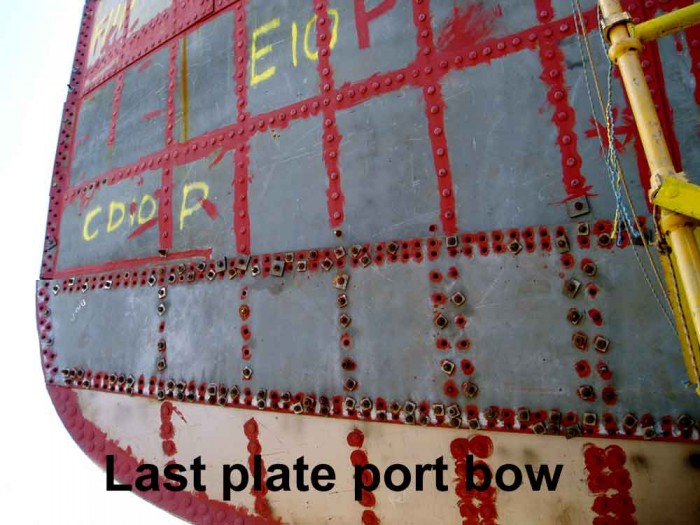
- This view shows the plate pulled into place. It is necessary to install 3/4" bolts in almost every second hole before the plate can be riveted. It is also necessary to run a bridge (tapered) reamer through every hole to ensure the red hot rivet will easily go into the hole during the riveting process
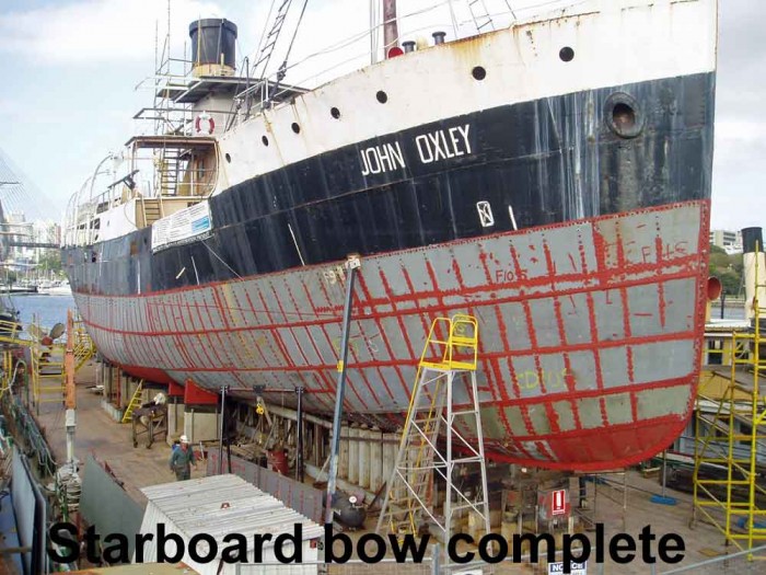
The Starboard bow has already been riveted up – as this is the most visible side of the ship and there has been much favourable comment from visitors to the site as well as from crews and passengers as they pass under the finished bow on their way to our other vessels.
Next task is to run the caulking chisel along the plate seams to achieve final watertight integrity. Volunteer blacksmith Andrew O’Connor has been active here bringing his unique skills to the project as he wields hammer on anvil to forge new caulking irons from old pneumatic chisels.
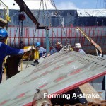
Work on A-strake
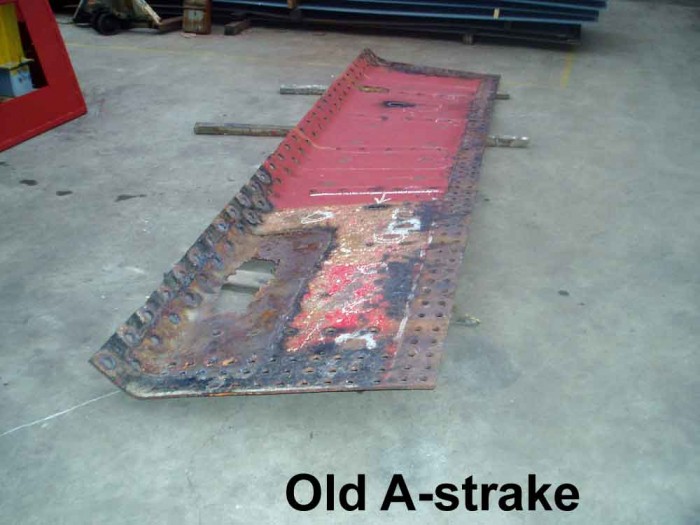
Replacement of A-strake, also known as the garboard strake, was always going to be a challenge.
Firstly the 750 odd tonnes weight of the hull is primarily taken on the keel itself. A support structure built from beams and struts has been erected to shift this load from the keel to structures further out. See also the How-it-is-done section on this.
A-strake plates have a flanged edge to enable them to be double riveted to the keel bar. Forming this flange required a long bend in heavy steel plate. We were not able to find a bender in industry that could handle the length required; therefore, we needed to build a forming machine to produce this bend.
Once again, we built a machine around our long-suffering Enerpac 50 tonne hydraulic cylinder. A working table that incorporated lifting attachments was designed and built. First tests revealed some additional supports were needed. The process is tedious but effective and produces a flange of the same shape and curvature as the original.
-
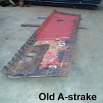
- Original A-strake plate showing wastage
-
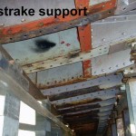
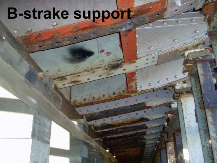
- Not easy to see, but it shows the support structure carrying the weight of the hull through the B-strake rather than through the bar keel on the left
-
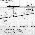
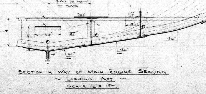
- Original plan showing Keel, A-strake, B-strake and Floor/Frame structures
-
- 50 Ton Enerpac hydraulic cylinder and forming table used to progressively shape the flange. The part-formed flange can just be seen on the left

The other difficulty is that the flange is not all the same angle due to the changing shape of the hull. This requires careful gauging of the flange angle during pressing.
Drilling many hundreds of 1″ diameter holes in a very awkward location is a challenge. Once again, we are relying on the tenacity and strength of our workforce plus a range of magnetic base drills to produce these holes.
The replacement of each plate becomes a project in itself. Firstly the old plate must be removed by oxy cutting out each rivet. The considerable weight of the released plate must be handled as it is transferred to the workshop for replication.
A new plate is drilled but the biggest problem centres on determining how to arrive at correct hole spacings and position for the keel rivets. Normally these are drilled on the job, but we are experimenting with different ways of pre-drilling these in the workshop.
When the A-strake plates are riveted in place, the weight of the ship can be re-applied to the Keel and A-strake so that the remaining B Strake plates can be fitted.
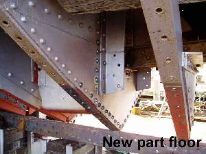
Overhaul hull structure under the 45 tonne main engine
There is an amount of plating and structural work required in the lower engine room. Unfortunately much of this is directly beneath the main engine.
The main engine is estimated at around 45 tonnes. This is a significant and concentrated load. Supporting a load of this size is straightforward; however, a bigger problem is the need to keep the bedplate as straight as possible to minimise future crankshaft axis alignment problems.
To achieve this, a structural support plan has been drawn up. First task was to get as much hull plating around the engine room, and above the bilge keel blocks, riveted firmly back in place and providing a measure of support.
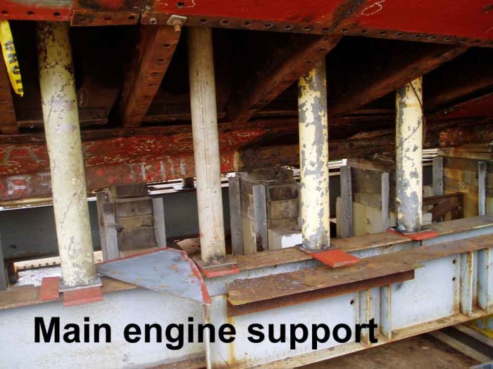
Another degree of support involves building a support grid of large rolled steel beams under the main engine. Heavy steel struts sit vertically on these supports and support the engine base plating via steel wedges.
-
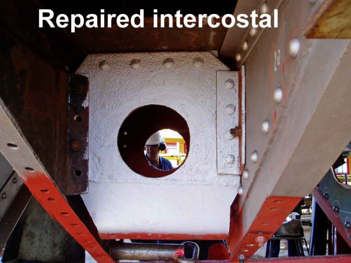
- New lower section welded to original intercostal member Note worker framed in the lightening holes is Brian Jaegar, volunteer visiting from the Campbelltown Steam Museum at Menangle to see how we rivet

Next task is to progressively crop and repair structures piece by piece so as to retain as much strength in the existing ship as possible.
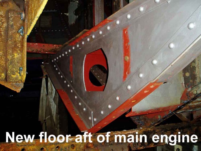
Away from the main engine, it has been possible to replace entire frame and floor (vertical plates) sections. But directly beneath the main engine, it has been necessary to minimise the amount of material removed so as to keep as much residual strength as possible.
When working under the main engine, the workforce is careful to only remove one section of metal at a time and get it back again and welded/riveted before starting on the next repair.
All of this work on the hull is a truly remarkable accomplishment and a credit to all involved. Thank you to our workforce, to our sponsors and to those who help in so many other ways.
ENGINEERING
Engine reassembled – note heavy-duty internals
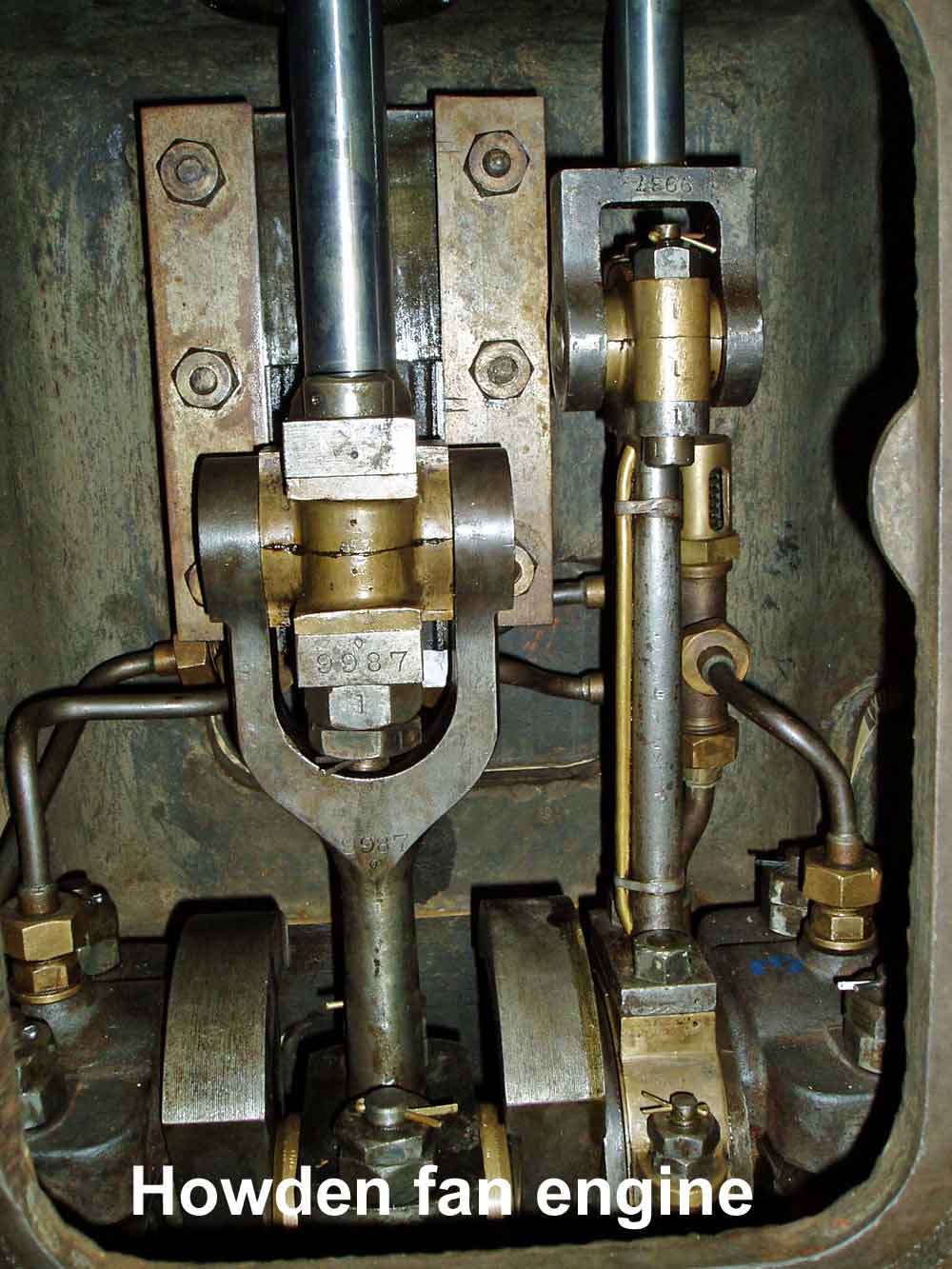
Fan and fan engine
The fan supplies a large amount of low-pressure air to the boiler furnaces. The Howden enclosed steam engine with its 54″ (1.3m) centrifugal fan is now completed and only awaits cosmetics.
Volunteer Don Harvey undertook the task of dismantling the fan, its casing and associated ducting. This required the removal of many hundreds of 3/8″ rivets so that the faying or joining surfaces or laps could be cleared of rust busts. Don, along with a team of volunteers then re-riveted the entire assembly back together again. Final task was to get the various parts grit blasted and painted, a task undertaken by sponsors Saunders International.
The steam engine that drives this fan is a Howden enclosed design and is of very robust construction. This engine has been overhauled by volunteer engineer Wes Mallitt and has needed the usual repairs, including a reground crank, re-metalled main and bottom end bearings, hard-chromed piston and valve rods, new piston rings and much TLC.
Main boiler feed pumps
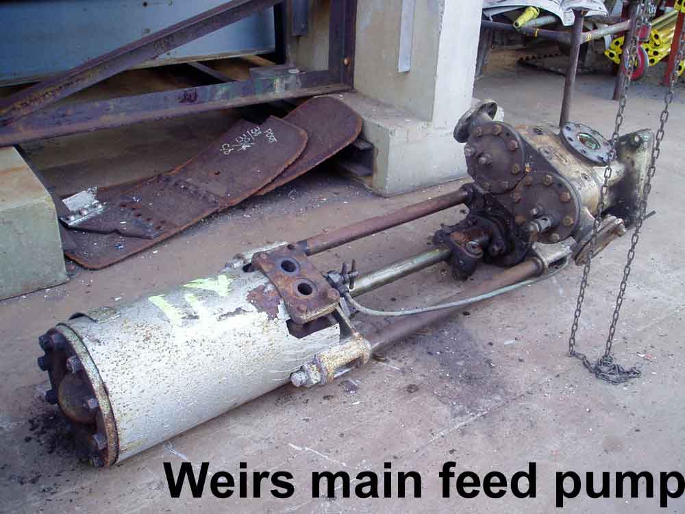
Main feed pump just after removal, prior to dismantling and rebore
The feed pumps are of critical importance in any steam plant. John Oxley is fitted with a set of Weir vertical feed pumps. While they still worked well, it is sensible to remove and completely overhaul this set.
First task was to overhaul the Weir shuttle valve chests. We have three – two are installed on pumps, while the third will be bolted to the bulkhead (usual practice is to keep one as an emergency spare).
The steam and pump end cylinders were all in need of a rebore and were taken up the road to Hallidays Engineering at Balmain. The pump cylinders (bronze) were then honed using a flexihone. The steam cylinders (cast iron) needed a more industrial approach and were honed at Meekes Honing at Wetherill Park. New pistons and rings are currently being manufactured.
Fire & Bilge pump
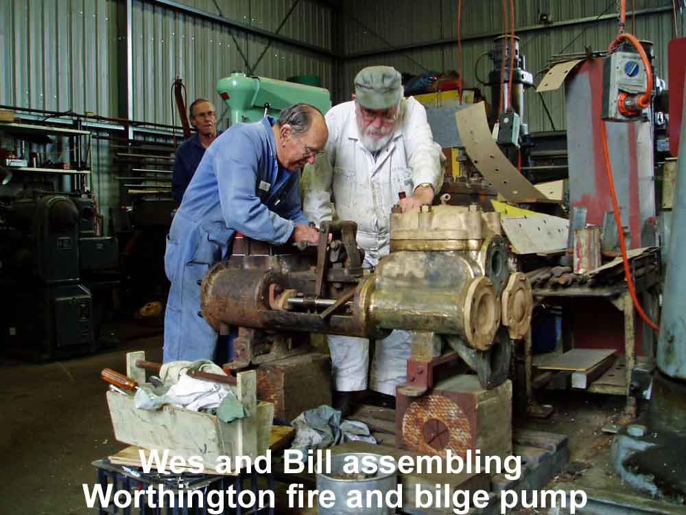 As the ship was built under 1927 Lloyds Rules, John Oxley was originally fitted with two steam powered fire & bilge pumps. Later, a change in regulations required that a third pump had to be fitted, so the Queensland Harbours and Marine installed a Worthington duplex steam pump.
Restoration of this pump commenced many years ago, but was halted due to funding issues. Work has restarted and the pump is almost complete. Water end, steam valve chest and rods have been overhauled. Steam and pump cylinders have been rebored and new pistons and rings are underway.
Circulating pump engine
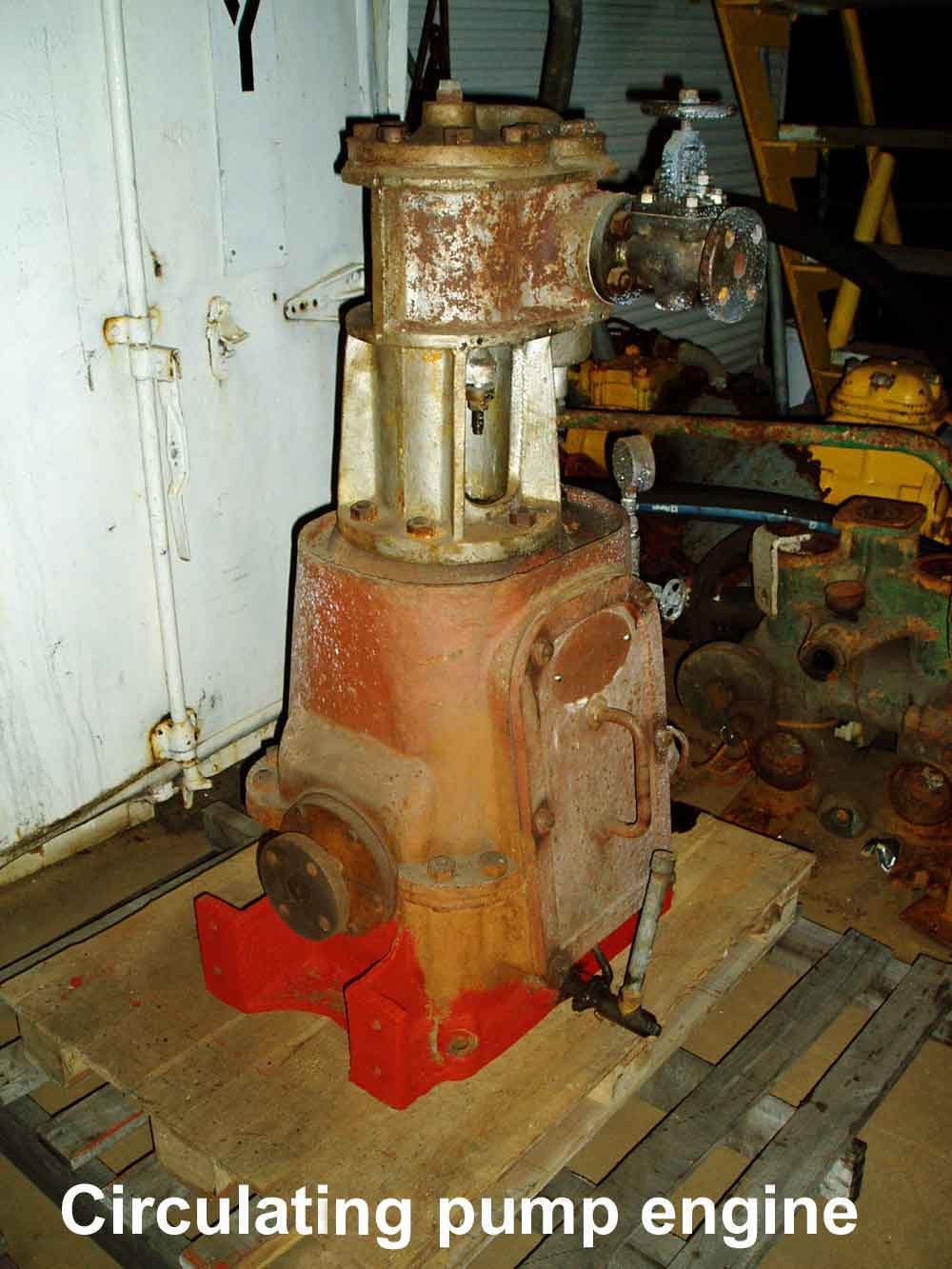
Matthew Paul circulating pump engine before restoration
The engine drives the 9″ centrifugal pump that supplies the large amounts of seawater needed to cool the condenser. This auxiliary engine is usually the first auxiliary engine started, and the last stopped and must be totally dependable.
We suspected that earlier restorers had been busy inside this engine, but we weren’t sure how much had been done. Again, Wes has pulled this engine down for inspection. We found the engine had been extensively overhauled and would need only cosmetic work plus new cylinder lagging and sheet steel cleading.
John Oxley has an impressive number of steam engine manufacturers represented on board. Shipbuilders Bow McLachlan built the hull, boiler and main engines, As specialist builders of steering engines for merchant and RN vessels, they also supplied the steering engine (and one to S.T. Forceful in Brisbane as well).
We also have Weir feed pumps, Dawson & Downie shuttle valve air pump, duplex fire & bilge pump and one big duplex ballast pump. There is a Sisson engine / Crompton dynamo set, a Howden forced draft set, a Reader engine / Sterne fridge set plus the later fit Worthington duplex fire & bilge pump.
One of the really interesting things about our sort of work is getting close and personal with each engine and seeing how the original designer solved engineering design problems. This is certainly the case with the Matthew Paul circulating pump engine, where one is certainly impressed with the generously proportioned components inside this heavy duty engine.
Bilge systems
The ship must be able to pump bilges from the day it is relaunched and at least two pumps, one steam (air as well) and one electric will be fitted.
The original bilge system was completely unusable. The cast iron suction manifolds had rust wedged themselves apart. The cast iron suction pipes were almost completely blocked with rust and deposits and the heavy lead bends were badly dented to the point where water flow was affected.
New bilge suction manifolds have been cast by sponsors Wallbanks Foundry from patterns made in our woodworkers shop by Ken Bryant, our volunteer patternmaker. The castings were then machined and fitted out with the original internals. A start has been made on new bilge suction pipes in galvanised steel.
Overhauled pumps, manifolds and piping systems will be installed as soon as the hull team have finished their work in the lower part of the hull.
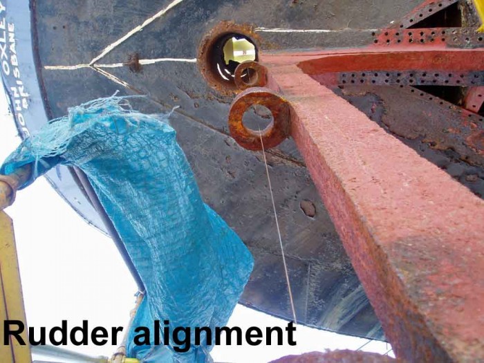
Rudder and stern frame
The engineers need to overhaul the rudder and steering gear and as well verify that the rudder and stern frame are in correct alignment.
The rudder is having a new upper plate welded-in due to wastage at the working water line. New pintles have been machined in the workshop by Bill Shepherd, our volunteer machinist.
A wire has also been strung down the axes of the rudder and the stern frame to check that the components have remained straight.
-

- Removing the wasted top plating of the rudder

-
- Wire stretched tight to verify rudder post alignment
Other problems in the steering gear concern localised wastage of the rudder head and tiller. A welding procedure has been drawn up by the Welding and Technology Institute and so far, the tiller has been padwelded back to original size. We are waiting for a final magnetic particle crack testing procedure before getting this component signed off as repaired. Next task is to pad weld wastage that has occurred to the rudder head shaft.
Volunteers and volunteering

Driving 1″ rivets into the forefoot, using two rivet guns
The core of skills needed to restore and then operate heritage ships is diminishing in the broader community.
A vital part of Sydney Heritage Fleet work is the preservation of traditional skills through restoration work on actual heritage vessels and much of this work is learnt and practiced by keen and enthusiastic volunteers.
Heritage Fleet volunteers come from all walks of life and consists of both the young and not so young. We have men and an increasing number of women on site – all are united by the drive to progress work on John Oxley.
Some of our workforce bring valued ship repair or similar skills to the project – many others turn up and quickly learn useful skills on site that makes them very productive volunteers.
Those who wish to join up can contact our office on 9298 3888 and ask to attend our next tour group. Main work days are Tuesdays, Thursdays or Saturdays – visit on one of these days and ask to speak with one of the team leaders.
Supporting the project
Most Sydney Heritage Fleet projects start with a vessel, which is then surrounded by a group of people.
People are the mainstay of our business. They initially become inspired to commence and then build a project. Other people enter the project as workers, sponsors and enthusiasts. People are clearly the most important resource this organisation has.
Firstly we have the need for physical workforce on the project. We need fabricators (skilled, unskilled and semi-skilled), engineering types, painters, restorers and more recently, people skilled in office work.
Secondly, we need sponsors and people that are enthused and actively supporting the project. These people work on the project through supply of goods and services, assisting us through complex government legislation, and through direct injection of funds.
The challenge for us is to build a positive project ethic that encourages this support from volunteers, sponsors, business, industry and government.
Another challenge is to build a project that connects all of these people together. The workforce is already on site, and enjoys working on the project plus the social interaction. We urge our off-site supporters to become on-site supporters. Please drop in and make direct contact – we suggest you call first to ensure you are connected with the right people.
If people are in a position to join in, please make contact through (02) 9298 3888.