John Oxley Artefacts
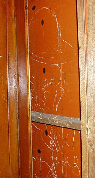
Bowler-hat cartoonAn interesting discovery was made during the dismantling of the panelling in the Pilot quarters. Inscribed on the steel plate behind the panel is a picture of a man in a bowler hat. In the days that the ship was build, 1927, it was customary that the Foreman wore a bowler-hat and a three-piece suit. The hat was in part a status symbol, and in part a basic “safety helmet” as protection against the accidental and “accidental” dropping of tools, bolts and rivets by the workmen. |
 |
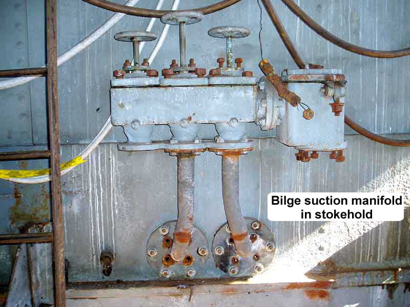
Bilge suction manifoldOriginal cast-iron bilge suction manifold in the stoke-hold. A number of these manifolds are distributed over the ship. They allow the engineering crew to control the inlet source to the suction water pump in the engine room |
 |
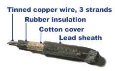
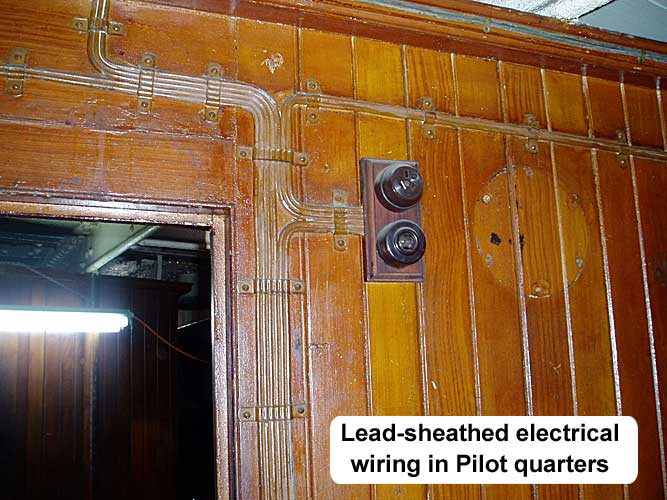
Lead-sheathed electrical wiringThe ship was fitted with a 110 Volt DC electrical generating system. The electrical current was distributed via lead-sheathed electrical cable. The insulation between the conductors and the lead-sheath is by rubber and a cotton cover. Each conductor consists of 3 strands of copper wire. In the latter years of the operational ship, numerous short circuits to the sheath were reported in the electrical system. The lead-sheath was not always properly grounded! |
 |
 |
Delivery logbook, 1927 |
| Click here to see images of the relevant pages from the logbook for the delivery voyage from Greenock in Scotland to Brisbane in Queensland, Australia.The voyage took about 2 months with re-fuelling in a number of ports. It is interesting to note that the wife of the Master is listed as stewardess in the crew list. |
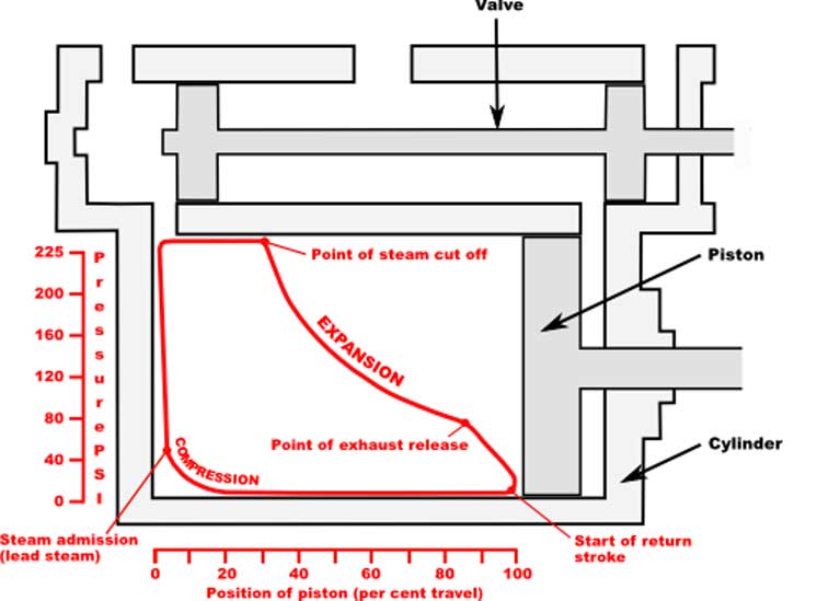
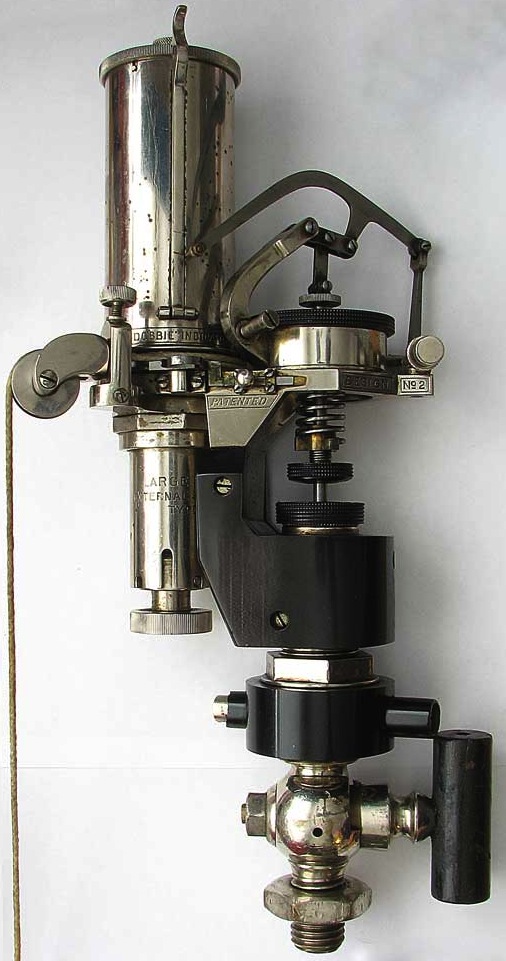
Steam engine power indicatorThe drum, in the upper left of the indicator, is fitted with paper card. The pencil will chart an X-Y diagram. where the horizontal X-axis records the movement of the piston via the string that rotates the drum. The vertical Y-axis records the corresponding steam pressure in the cylinder against the spring to the pencil, through the parallel linkage above it. The indicator has in its case a number of springs that can be changed according to the expected steam pressure in the cylinder. |
 |
 |
Mean effective pressure, pm:
| pm (lb/in2) = | area of PV indicator card (lb/in2)(in3) _____________________________ swept volume of cylinder (in3) |
Indicated Horsepower, ihp:
| ihp = | pm L a n _________ 33,000 |
| Where: | |
| pm = | mep, lb/in2 |
| L = | stroke, ft |
| a = | piston area, in2 |
| n = | number of cycles per minute |
| 33000 = | ft-lb/min/ hp (definition) |
Note the formulas and diagram were obtained respectively from here and here, where more information is available.